
 Several years ago Benjamin proposed a system of sensors inside the habitat measuring all necessary parameters like oxygen, carbon dioxide etc. and communicating among each other. Last days we talked about it again and found out, that it would still be a good solution. So we decided to publish it here again. Below you find the original thread, translated from German:
(zur deutschen Version als pdf geht’s hier)
Suggestion from User Benjamin, 20.01.2007 at 22:02
For the realization of the sensors issue I would suggest a wireless sensor network (WSN). A WSN is a computer network of miniaturized microcomputers, so-called sensor nodes, which are equipped with sensors and co-operate with a certain task. The sensor knots (called motes) of the underwater station should have the following sensors:
For the realization of the sensors issue I would suggest a wireless sensor network (WSN). A WSN is a computer network of miniaturized microcomputers, so-called sensor nodes, which are equipped with sensors and co-operate with a certain task. The sensor knots (called motes) of the underwater station should have the following sensors:
- temperature
- pressure
- humidity
- fire alarm
- O2
- CO2
- changes on the outer shell of the station

Figure 1 shows the appearance of a mote in its current state of the art. The performance is similar to the first personal computers. The core of a sensor node is its processor with the associated memory (usually a flash memory) that is powered by a battery. In addition, the sensory equipment, ie one or more passive sensors, and, on the other hand, the communicative equipment. Generally a sending unit is provided for this purpose. In addition, sensor nodes have a multiplex unit as well as a system for data analysis.

Figure 2 shows on the left side a schematic representation of sensor nodes and their (idealized) radio range r. In order to deal gently with the available energy, each sensor node should only send as strong as necessary to reach at least two or three neighboring nodes. In this example it results in a connection graph as shown on the right side. If a node detects a measured value via one of its sensors, it can forward it to neighbors via its short-range radio technique. This next node will then forward the value until the value reaches a node, that is able to send it directly to the server of the underwater station and via GPRS (General Packet Radio service) to the Internet. With today’s mobile network, GPRS is almost everywhere available in many countries and is often used for data transmission. Alternatives are, of course, fixed networks or satellite radio systems. This could be used to monitor and control the entire monitoring by a control center on land.
Now, however, the question arises as to how the sending/receiving net behaves under water. Does anyone have an idea or experience?
Posted by Mart on 03.02.2007 at 18:13:
So, wouldn’t it be a good idea, if each mote reaches at least 2 more motes. So you could find out whether it is really a leak or a function disorder of a mote, right? What do the individual building modules cost? Now we absolutely need someone who is familiar with the individual sensors.
Posted by Benny on 05.02.2007 at 22:05:
Yes, that’s the nice thing about WSN’s. The working areas overlap. This ensures, that the work can be taken over by other motes in the broadcasting area, or that it can be monitored if a mote fails. For this it is necessary that they have the same sensors …
For the project, we use the Crossbow’s Development Kit (www.xbow.com). Eight motes, 2 gateways and accessories cost about 750, – Euro.
Posted by michaelgrasb on Feb 14, 2007 at 4:30 pm:
I do not consider radio in a permanent solution as useful, especially if we are talking about a new installation, in which all channels (e.g. cable routes) are open. Therefore my idea (with emphasis on IDEA): programmable controllers, which are for safety relevant applications with a VERY high failure safety. However, I would then interpret the whole set two times
Sensor on control 1,
Sensor on control 2,
Sensor on control 1,
…
These sensors should provide a 4 – 20mA signal, which has to be evaluated by the controller. This 4mA signal ensures that a fault is detected in the event of a wire break (0mA).
This should be only a first idea to be developed further.
Posted by Benny on 15/02/2007 at 15:33:
Wow, that sounds good! I do not really know about sensor technology and measurement technology. I have only encountered WSN’s in the course of my studies, which can also be equipped with a sensor and thus would have been an approach. But it was just an idea …
How do your sensors look like exactly? What is their interface? Would be great if you could describe them more precisely.
Posted by michaelgrasb on 15/02/2007 at 15:55:
I did not have any ‘special’ sensor in mind. It was only meant as a draft to be built on.
The interface is an analogue input to the controller. This control then knows, that it is connected to a 4-20mA sensor and that there has to be a minimum flow of 4mA, because otherwise a fault is present.
In our steelwork operation we use (almost) exclusively this technique. I’ll take the time tomorrow and make a small drawing, that shows in which direction my thoughts go.
At this point, however, I would like to point out that these are just my ideas. Whether this can be implemented (in terms of safety …) I can not guarantee at this point !!
Posted by michaelgrasb on Feb 16, 2007 at 8:06 am:
Here I am back again, as promised, with a very simple ‘paint’ sketch! (Unfortunately not available in higher resolution anymore, sorry! Mart)
 The sketch should represent the habitat under water (outside, blue-green) and has in the inner area 3 rooms + 2 technical rooms (control and oxygen supply) Each room has 2 sensors (2 equal (oxygen) sensors – green or brown). One leads to controller 1, the other to controller 2. These controllers regulate the two fans, whereby each of the fans is designed in such a way that it can supply the whole habitat (should one of them fail or need maintenance the proper function of the rest should be ensured)
In addition, the two controls are connected to each other (blue) to exchange information (current statuses) in order to avoid one fan running at 100%, the other at 0%, and to detect faults or the failure of a controller.
Posted by Benny on Mar 11, 2007 at 7:31 pm:
Did I understand it correctly … a sensor is connected to a control unit, which checks whether current flows. If the circuit is interrupted, it is clear that an error has occurred.
If this is the case, this seems to be relatively easy to implement.
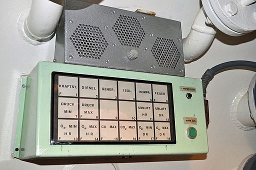
The image at the beginning of the article shows a control panel in UWL Helgoland; image source: User:Klugschnacker (Eigenes Werk) [CC BY-SA 3.0 (http://creativecommons.org/licenses/by-sa/3.0)], via Wikimedia Commons
Here are two links provided by user Frank that need to be followed up:
One is the Research Group Wireless Sensor Networks (WSN) and Internet of Things (IOT) at the Frankfurt University of Applied Science:
https://wsn.fb2.frankfurt-university.de/
The other one is the Crossbow Wireless Sensor Networks Product Reference Guide 2007 (pdf):
http://www.investigacion.frc.utn.edu.ar/sensores/Equipamiento/Wireless/Crossbow_Wireless_2007_Catalog.pdf